DUST DEPOSIT GAUGE
INTRODUCTION
The Directional Dust Deposit Gauge was developed in the United Kingdom - the background to the development being described in the article "The measurement in the field of pollution by dust" written by D H Lucas and D J Moore and published in the International Journal of Air and Water Pollution, Volume 8 of 1964. It was soon adopted by those interested in the effects of high voltage insulator contamination and the results of its initial use at the Brighton, Leatherhead, Wakefield, Carrington and West Thurrock insulator test sites are given in the Cigre publication Electra No. 20.
The gauge was selected by the South African national utility, Eskom, for the first insulator pollution survey undertaken in the country from 1974 to 1976. The comparison of the pollution severities measured and the performance of the insulation in the vicinity of each gauge facilitated the "calibration" of the gauge readings for meaningful interpretation of the data. Some 25 years later, it continues to be widely used by Eskom and others as an inexpensive yet effective tool to establish the overall contamination level of a site.
GENERAL DESCRIPTION
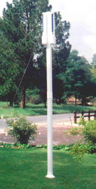
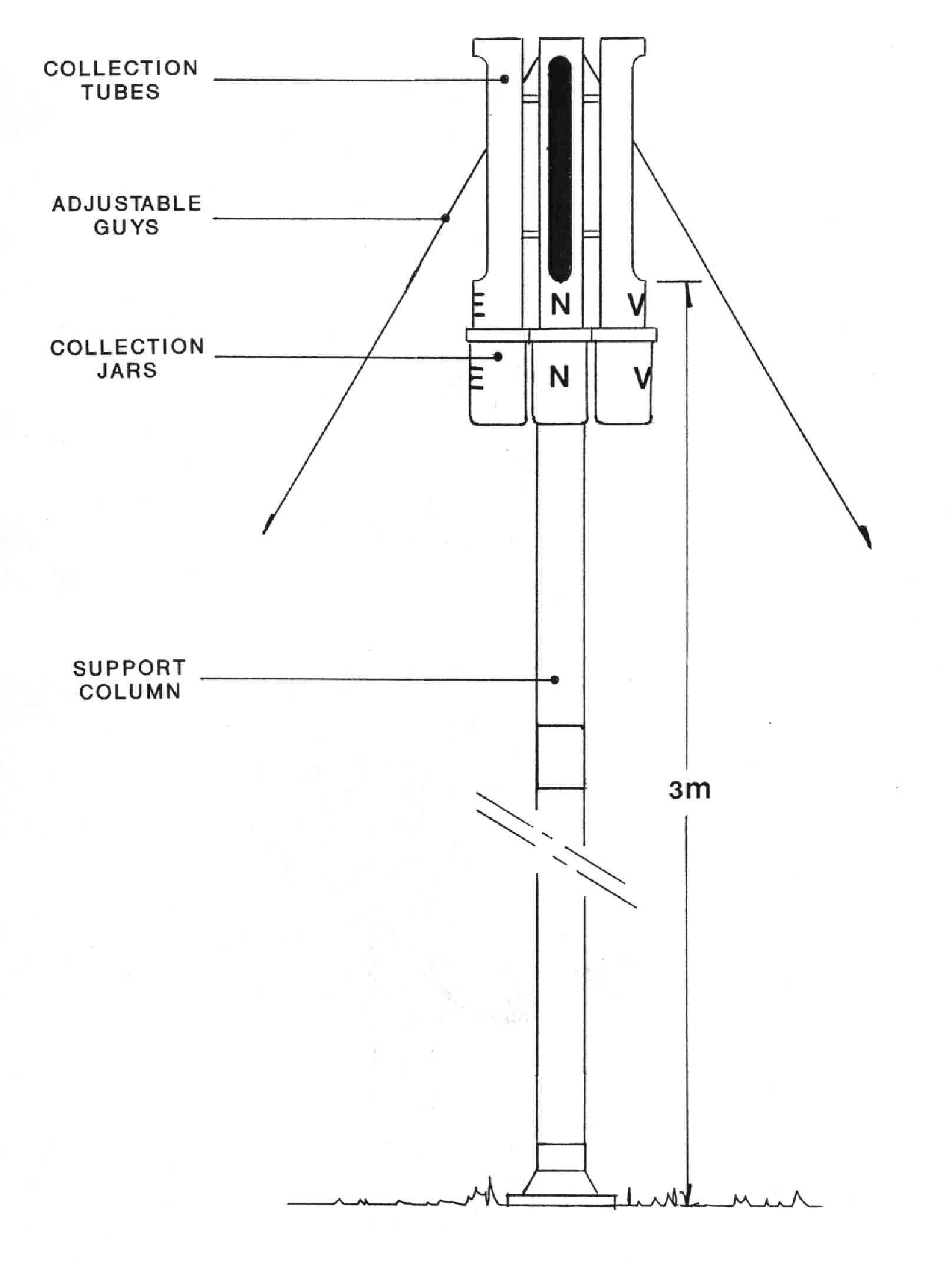
The dust gauge is comprised of four vertical tubes each with a slot milled in the side – these being so arranged as to face north, south, east and west. A removable container which collects the deposits blown into the slots is attached to the bottom of each tube.
The device was chosen for the first large scale insulator pollution survey in South Africa as it offered the following advantages over other techniques:
· The gauge requires no electrical supply or other energy source
· The gauges are relatively inexpensive thus permitting widespread measurements and, for example, numerous measurements along a line route
· Servicing of the gauge is simple and can be undertaken by local unskilled personnel.
In view of these advantages, the dust gauge has seen increasing usage by utilities and, as referenced in IEC 60815, has become a standard method for pollution severity assessment.
To facilitate international comparison of results, the slot sizes provided in the gauges manufactured by Mace Technologies of identical area to those originally employed in the United Kingdom and which are due to be standardised in the latest revision of the IEC Publication 60815.
CONTAMINANT COLLECTION
The collection efficiency of the gauge is greater for coarser particles and less for finer particles - the finest particles being swept around the gauge without leaving the air stream. This, however, is an inherent feature of the deposition of dust on objects in the path of the wind and thus represents a good simulation of the contamination of actual insulators.
The amount of material collected is also dependent on the wind direction. It is maximum when the wind is blowing directly into the slot and falls progressively to zero as the wind direction approaches 90 degrees to the slot. The gauge thus provides an indication of the direction of the origin of the contamination and facilitates discrimination between various pollution sources.
In wind tunnel tests to establish whether dust may be removed from the gauge in high winds, it was found that no particles in excess of 300um diameter could be extracted at wind speeds up to 25m/s (90km/hr). A finer sample, 76um to 150um, decreased in mass by a mere 0,47% after 5 minutes exposure to a wind of 25m/s directed at what was found to be the most critical angle of 60 degrees to the slot. The slight loss of sample is not considered significant. Moreover, at the high wind speeds required, it is felt that pollution removal rather than deposition would occur on the actual insulator surfaces as well.
GAUGE MOUNTING
The gauges can be supplied complete with stands or, alternatively, the tubes can be mounted on a central wood pole or any convenient existing structure positioned away from trees or other obstacles which could affect normal air flow.
Although the dust gauge should ideally be placed at the height of the insulators, this tends to be impractical for the regular, easy and safe exchange of the collection jars. Also, insulators are used at various heights for different applications and voltage levels. As the gauge yields a comparative, rather than an absolute, measurement of pollution severity, a fixed height which makes the jars fairly accessible but out of the way of casual tampering is preferred. In the initial surveys, the gauges were mounted such that the distance from the ground to the bottom of the contamination entry slot was 3 metres. This height has continued to be used ever since and has become the standard.
SERVICING OF THE GAUGE
The only action required of field personnel is the monthly replacement of the contaminant collecting jars and the return of those removed to the laboratory or depot for analysis. When the clean jar is fitted to the gauge, it must be ensured that it is identified with the name of the site, the tube direction and the date of installation. On removal, the date must also be recorded. Labels are provided for this purpose.
MEASUREMENT AND INTERPRETATION OF THE RESULTS
On receipt, a volume of 500ml of demineralised water is added to each jar. Should the jar already contain some rain water, the volume can be made up to 500ml with the addition of demineralised water. The water used should have a conductivity of less than 5µS/cm.
After shaking and allowing some time for all the soluble salts to dissolve, the conductivity of the solution is measured. As the conductivity of a weak saline solution is inversely proportional to its dilution, the measured conductivity is proportional to the product of the volume and conductivity of the original contents of the gauge.
The "Pollution Index" is defined as the mean value of the conductivities of all four directions, expressed in µS/cm and arithmetically normalised to a 30 day month. In terms of the classification of pollution severity defined in IEC Publication 60815, the dust gauge Pollution Index can be interpreted as shown in the table below.
|
Pollution Index (µS/cm) |
Pollution Class |
|
0 – 75 |
I - Light |
|
76 – 200 |
II - Medium |
|
201 – 350 |
III - Heavy |
|
> 350 |
IV - Very Heavy |
Apart from the establishment of the overall Index to categorise the site in terms of its pollution severity, it may prove of interest to study the results from the different compass directions or to undertake chemical analyses of the contaminant collected. If the solutions from the jars are filtered and weighed, the non-soluble deposits, or NSDD, can also be determined.
CONCLUSION
The Directional Dust Deposit Gauge represents a simple, inexpensive method of classifying sites according to their pollution severity. As contaminant levels can vary widely over a small area, their use in the planning stages of a line or substation will assist in the selection of the correct insulation or, for example, may indicate that a minor change in location can significantly improve insulation reliability.
Dust Gauge results can also be useful in gaining more detailed information on pollution sources, their effects on high voltage installations in the vicinity, the timing and extent of maintenance procedures and/or the insulator upgrading or replacement necessary to provide the required system security.
The standard Mace dust gauge kit comprises:
4 x Measurement Tubes
8 x Collection Jars
4 x Jar Lids
1 x Two-piece mounting stand with base, coupling and top cap
4 x Adjustable Guy Ropes
4 x Ground Pegs
48 x Jar Identification Labels
4 x Tube Mounting Rods, Nuts and Spacers
Optional:
Digital conductivity meter with automatic temperature compensation.

HOME
INSILCOTE
INSILCURE
HAWKEYE
REDEYE
COND JOINTS
![]()
CONTACT US